Wednesday, January 26, 2011

Pathloss 5 - Import links from text file

Step 1 - Open text (CSV) file

Click View - Site List to bring up the Site index. You can also click the Site list button on the toolbar.


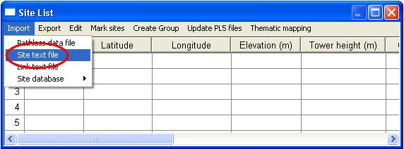
Click Import - Site text file


A file open dialog box will appear. Select the text file you would like to import and click Open

Step 2 - Select text file type

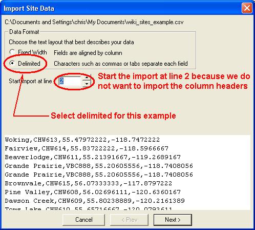
This is a comma delimited file with column headers. Select Delimited and because we do not want to import the column names, set Start import at line to 2.


Step 3 - Select delimiter

Click the Next button. Make sure that the delimiter is set to Comma and click the Next button.


Step 4 - Assign column names

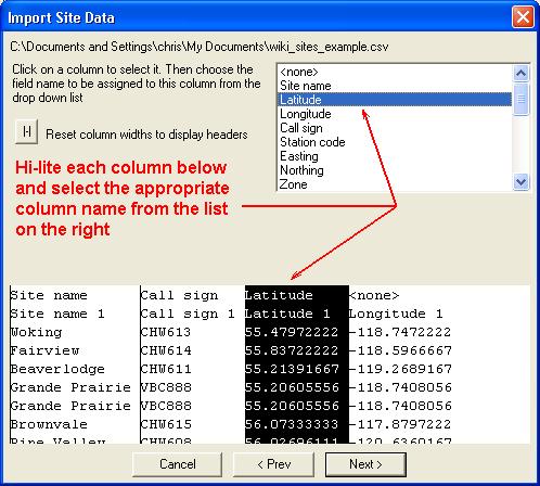
Click on a column to select it, for each column you need to:


Select the appropriate data category and then select the column name to assign.

Note: It may be useful to leave the "Start import at line" from the second step above at 1. This will make assigning the column headers much easier. One the assignments are complete you can click the


Set the location (Site 1 or Site 2) and click Assign to column


Once all columns have been assigned, you can save these import definitions in a file. This file should be included with the text(csv) file when sending to other users.


Step 5 - Verify coordinate and group settings

For this example we need to set the Longitude to +East. Normally the Eastern hemisphere is positive and the Western is negative. Depending on the source of your coordinates you may need to change the hemisphere you are in to positive. The same applies to Latitudes and whether they are in the North or South hemisphere.

At this point you can also specify the group you would like the sites to appear in, or you can also create a new group to add the sites to. For more of groups see Pathloss 5 - Using groups


Click Finish to import the sites into your site list.


Thursday, January 20, 2011

Pathloss 5 :Import sites from text file

This is a step by step procedure for importing site text files. Usually the site text files are delimited with commas or tabs, but they can also be fixed width. Pathloss 5 is flexible enough to read either.


Example link text file in CSV format:


Site name,Call sign,Latitude,Longitude

Woking,CHW613,55.47972222,-118.74722222

Fairview,CHW614,55.83722222,-118.59666667

Contents [hide]

1 Step 1 - Open text (CSV) file

2 Step 2 - Select text file type

3 Step 3 - Select delimiter

4 Step 4 - Assign column names

5 Step 5 - Verify coordinate and group settings


Step 1 - Open text (CSV) file

Click View - Site List to bring up the Site index. You can also click the Site list button on the toolbar.

Click Import - Site text file


A file open dialog box will appear. Select the text file you would like to import and click Open


Step 2 - Select text file type

This is a comma delimited file with column headers. Select Delimited and because we do not want to import the column names, set Start import at line to 2.


Step 3 - Select delimiter

Click the Next button. Make sure that the delimiter is set to Comma and click the Next button.


Step 4 - Assign column names

Hi-lite each column and while it is hi-lited, select the appropriate column name from the list on the right.


Step 5 - Verify coordinate and group settings

For this example we need to set the Longitude to +East. Normally the Eastern hemisphere is positive and the Western is negative. Depending on the source of your coordinates you may need to change the hemisphere you are in to positive. The same applies to Latitudes and whether they are in the North or South hemisphere.

At this point you can also specify the group you would like the sites to appear in, or you can also create a new group to add the sites to. For more of groups see Pathloss 5 - Using groups

 Click Finish to import the sites into your site list.

Pathloss 4.0 Frequently ask

11. ) SUBJECT : 10 m DEM


Question :

Where do I find 30 and 10 meter USGS DEM sources that are compatible with Pathloss? (1:24000 scale 7.5 minute sources).


I have looked at the USGS web site and everything is using SDTS DEM which are tar'd and gnuzip'd (xxxxxxx.DEM.SDTS.TAR.GZ). These files, when extracted become .ddf files and these are not compatible with PathLoss. The USGS explains that the previous DEM files had coordinate adjustment errors so I don't want to look at old DEM files.

Answer :

Try www.micropath.com

If you haven't found this already, you need to get this nifty little utility.


SDTS2DEM.exe

First you use WinZip to extract all the .ddf files from the xxxxx.tar.gz file,

then you run the SDTS2DEM.exe program (under DOS) to convert it to a xxxx.dem

file. Then, you can go in to the PathLoss Database menu system and do an

ASCII to Binary conversion on the DEM file that you just created. It will convert it

into a file format that it can use - probably a .dta file.


Works on the 10meter files, but I've had no luck with the 30meter files. But, I'm

using Ver 3.0 of PathLoss, not 4.0.


I get all my SDTS files from GISDataDepot


http://www.gisdatadepot.com/catalog/US/sublist.html


12. ) SUBJECT : HYBRID DIVERSITY

Question:

In Pathloss 4, antenna configuration:TR-TRTH or TRTH-TR is defined as for a hybrid diversity configuration which uses frequency diversity in both directions and space diversity at one end of the path only.


In ITU P.530-8 the FD+SD diversity is specified for 2 receivers and 4 receivers separately in calculating outage probability. I used the above antenna configuration for 2 receivers, but I couldn't find any calculation for 4 receivers in Pathloss.


I'll appreciate if anybody can help me with this. Thanks.


Answer :

The configuration you describe is Quad Diversity. Antenna configurations should be TXRX-TXRX and configured with nominal SD. In the Worksheets module select Operations Diversity Calculation and specify the frequency diversity difference.


The resulted Worksheet Report will provide the effective receive level and reliability for Quad Diversity for each receiver.

Tank you very much for the reply. As a matter of fact, I had tried to use TRDR-TRDR configuration and specify the FD spacing for calculation before I posted the question in the Forum.


Unfortunately, the calculation result was not much different from that of 2-receiver. Moreover, it did not match the hand calculation that I did on the Excel worksheet according to ITU P.530-8 recommendation, either. Any idea?

If you check the help under antenna configurations it will show TXRX-TXRX as two antennas at each site both transmitting and receiving. Most Quad configurations that I have come across transmit one frequency on each antenna with two receivers, one on each receive frequency.

TRDR-TRDR is normally used for space diversity, Where the second antenna is receive only.

Hope this helps. Try it again with TX-RX and see if the results are more in line with your spread sheet.

Pathloss 4.0 Frequently ask

9. ) SUBJECT : ANTENNA POLARIZATION RATIO


Question :

On the manual books refered to interference chapter said that " the ratio of horizontal and vertical polarized signals is unknow. And all data are on those links that are analysed.

Answer:

the paragraph that you mention introduce the details of the below calculations.

Effectively the transmit antenna is not perfect and radiates the expected signal on one polar and also some energy on the alternate polarisation; let's say:

Expected signal is V polar; then the alternate radiated signal is H polar of which the power ratio is given by the VH curve

Similarly the receive antenna will also capture some H polar signal to the V port with the HV gain curve

Consequently, it is relevant to calculate the different combinations between interferer and interfered signal from both Transmit and Receive antenna and to select the minimum antenna cross-polar decoupling gain in order to evaluate the interfered received signal

Obviously, this is a worst case calculation because antenna manufacturer indicates antenna mask performance and a particular interferer captured on the corresponding azimuth and site angle will very often be received lower than calculated

But it is the standard method that should be applied to perform interference calculation

10. ) SUBJECT : VIGRANTS BARNETT CLIMATIC FACTOR (cf) & ITU-R RELIABILITY METHOD

Question:

What is the best way to determine the climatic factor (cf) in the Barnett & Vigants reliability formula? Not the C Factor!

Standard values seem to vary from 0.5 to 1 and 2.

How can we determine the exact value depending on the climatic conditions of a specific area?

I am especially looking for many areas in the province of Quebec in Canada.

Where can I find a climatic factor map?


Answer:

Maybe maps for the climatic factor cf do not exist (are not published). Then use instead the C factor with associated maps. The C factor is also by definition equal to cf for average terrain rouhness S = 15.2m


For a more detailed calculation you can use one of the newer ITU-R P.530 reliability methods. These are applicable worldwide

Thanks a lot Lars for your reply and your suggestion about the climatic factor for reliability calculation.


I only began to compare the ITU-530 methods with the Barnett & Vigants method.


Which method is the more reliable after you? 530-6 or 530-7/8 or the newest 530-9 ?


I get similar results when the path inclination is near 0 mr, but I get very different results when the path inclination is about 10 mr. What do you think about this?


Thanks a lot for your collaboration

ITU made a lot of changements over the last years for the recommendation P530. Therefore, if you are sure what kind of parameter set for the Barnett&Vigants is correct for your area you can choose this model.


If you have no idea the P530-9 recommendation gives a detailed model where you only need the data provided by ITU and the GTopo30 DTM from USGS to get the right parameters. You do not have to look anywhere else. This model seems to be proved with hundreds of hops all over the world. Nevertheless there will be a new recommendation P530-10 soon. Let's see what will be new this time.

Rejean, here is my comments to the three ITU-R P.530 reliability methods implemented in PL4.


P.530-6(detailed planning)uses an average grazing angle which for many(most) paths is ambiguous or even meaningless.


P.530-7/8 does away with this average grazing angle. Instead many link classes are introduced, which makes it somewhat cumbersome, especially for coastal links.


P.530-9/10 (detailed link design)uses a terrain database (GTopo30) and the refractivity gradient data are incorporated in PL4. This makes the method convenient in use, but the method itself and/or the PL4 implementation may be unreliable (see the thread in this user forum initiated on Sep.13, 2002 by AK).


At present I regard P.530-7/8 to be the most reliable method.

Thanks a lot Mike for your reply.


I will use both methods (Barnett & Vigants as well as ITU 530-9) and compare them on each link. Then I will probably be able to take a better decision.

Thanks for your comments about each ITU method.


The main point I am wondering about is why the path inclination has such an effect on the reliability result?

ITU 530-6 and 530-7/8 are the only two methods using this parameter.


I get 99.9999% compared to 99.999% if the path inclination is respectively 10 mr instead of about 1 mr. Is it the reality?

In general a high low path is more reliable than a path without any inclination. The reason for this is the less high probability for multipath with a certain inclination.

Pathloss 4.0 Frequently ask

7. ) SUBJECT : BEST POLARIZATION OVER THE WATER


Question :

Regarding with the best polarization in microwave links over sea water; I’ve learn is Horizontal don’t remember though. Can somebody send me theory documentation about that?.

Anwer:

This is news to me. In link design over water the major issue is Reflections since water is a plane reflector. For Frequencies below 10Ghz Polarization is considered only for frequency planning purposes. Polarization is usually an issue in links at frequencies above 10Ghz. Horizontal stretcxhing of rain drops usually make the horizontal polarizated signal get slightly more attenuated than vertical

The underlying principle is that a wave travelling over a surface has currents absorbed by the surface.


A horizontally polarised wave has more ground absorbtion than a vertically polarised wave.


A vertically polarised wave over water has more absobtion than a horizontally polarised wave

The issue here is conductivity of the surface. The more conductive the ground is, the stronger the reflection will be (and therefore cause more multipath problems).

Reflections from sea are thus more critical than reflections from terrain with vegetation.By selecting vertical polarization for over-the-water links, you can achieve 2-17 dB reduction in surface relection in comparison with horizontal polarization.

"conductive - having the quality or power of conducting heat or electricity or sound; exhibiting conductivity"

A vertically polarised wave over water has more absobtion (less reflections) than a horizontally polarised wave. A conductive surface will absorb a wave, not reflect it. Hence a vertically polarised wave will have less reflections.


Bottom line - verticle over water

your statement: “A conductive surface will absorb a wave, not reflect it” is contradictory to any known electromagnetic wave propagation theory. I will try to illustrate my point without getting into beautiful Maxwell’s equations, Faraday’s equations and other fun things.

Generally speaking, for a plane electromagnetic wavefront (EI)incident on a plane boundary between two different dielectric media having different refractive indices (n1 and n2), part of the energy (ET) will penetrate the second dielectric (refraction) and part of it (ER) will be reflected back (reflection).


ER = EI x (n1-n2)/(n1+n2) ET = 2EI/(n1+n2)


Consider a plane wave falling normally on a flat metallic surface and hence, the case of refection from a (perfect) conducting surface:


ER = - EI ET = 0


For good conductors n2 is a large number, tending towards infinity in the case of a perfect conductor. Therefore, no field is transmitted into the metallic medium, and the field is fully reflected back with a 180ยบ change in the phase of the wave (due to the minus sign).

This is exactly the principle waveguides use for electromagnetic wave propagation. They must have perfectly reflective and conductive coating on the inside to function properly.


Conclusion is that more conductive the surface, more electromagnetic waves will be reflected from it.


The extreme case is a totally metallic surface in which absolutely ALL of the energy gets reflected.


TEST PROCEDURE FOR DRY TESTING ODU OF SRAL RADIO


The correct way to test the SRAL units is as follows.

1. You will require two -48VDC power points for the two SRAL IDU units.

2. You will require two IF cables to connect the IDU’s to the two ODU’s

3. There needs to be a RF connection between the two ODU’s to complete the link. This is also known as a virtual link. If the test is done without this link you stand a good change in damaging the ODU because of high VSWR levels.


The virtual link for a 7GHz SRAL test scenario consists out of the following.


2 x Waveguide to Coax Transitions (Flange = UDR84 / Waveguide = WR112 / Coax type = Type Female(FM).) (Order number from Andrew = C122LNSG)

2 x RF attenuators (0 to 12GHz) 30dB N-Type Male to Female (To obtain a nominal receive level of -40dBm (+/- 5dB)) (Order number from Huber+Suhner = 22550187)

1 x RF test cable 1meter (Sucotest Straight plug N-type male to male (DC up to 13GHz)) (Order number from Huber+Suhner = 23005046)


The virtual link will be arranged in the following way.


Starting from left to right.


1. #1 ODU (UDR84) to #1 Waveguide to Coax transition (UDR84)

2. #1 Waveguide to Coax transition (FM) to #1 RF attenuator (M)

3. #1 FR attenuator (FM) to #1 RF test cable (M)

4. #1 RF test cable (M) to #2 FR attenuator (FM)

5. #2 FR attenuator (M) to #2 Waveguide to Coax transition (FM)

6. #2 Waveguide to Coax transition (UDR84) to #2 ODU (UDR84)

8. ) SUBJECT : EFFECT OF TOWER GUY TO MICROWAVE LINK

Question:

Can we really have a problem in the field when a microwave antenna is installed on a tower, just below the attachment point of the guys, and that the azimuth of the antenna is about the same as the azimuth of one guy ?

If yes, what is the minimum angle to respect between the antenna azimuth and the guy azimuth compared to the antenna beamwidth for example ?

If yes, is there a minimum distance to respect between the antenna and the guy in order the negative effect disappears ?

What about the possible accumulation of ice on the guy ? The ice can surely becomes a significant obstruction to the antenna!

Is there any practical or theoretical standard about this phenomenon ?

Answer:

When you use microwave parabolic reflector or horn antennas, you should be aware of the 100% path clearance in the near-field area (also called the Rayleigh zone) where the radiated waves are travelling inside a cylinder that continue the dish circle (the dish is then the radiating surface of a planar wave that is a zero-loss propagation mode)


The distance of the Rayleigh zone is given by a simple equation:

dR= D²/2*Lambda where:

dR: distance of the Rayleigh zone

D: antenna diameter

Lambda: wavelength

in the Rayleigh zone the Radiated Power Density is constant along the distance (zero-loss propagation)


the next zone is the Fresnel-Kirchoff zone that extend between dR and dFK with

dFK= 2D²/Lambda


in this zone the Radiated Power Density is fluctuant


the last zone is the Fraunhoffer zone where the wave is now spherical and the Radiated Power Density decay according the 1/d law; yhis is the far-field zone


Conclusion:

Free space loss is computed with assumption of the far-field propagation.

You should avoid to place any obstacle inside the Rayleigh zone. Otherwise big impact in term of:

RPE (radiated pattern enveloppe)distorsion

Cross-Polarisation degradations

Another thought....


With the guy wire returning to ground, it would act as a parasitic element and absorb the radiated energy. The net result would be a field strength distortion / reduction in the desired direction.

It looks like this thread was done some time ago, but I thought I would add one other interesting point.


We once had a guy going through a u-wave path that seemed to either reflect or retransmit the signal causing interference not in the adjacent hop, but in the next hop around the loop (we were using the standard 2-frequency plan). It made no sense at the time, but when we replaced the guy with a non-metallic material, the interference went away.

My rule has always been a minimum of 10 degrees for highly directional microwave, just to make sure you are nowhere near the guy.

Tuesday, January 18, 2011

Frequently Ask Pathloss 4.0

4. ) SUBJECT : SURGE SUPRESSOR PLACEMENT
Question :
in an installation with IDU-ODU linked with an IF cable using 2 surge arrestors. One next to the oDU and another at the building entry plate, what is the Surge arrestor next to the ODU protecting? ODU or IDU?
Answer :

very late reply, but just in case you still have a problem.... The sign on a surge unit named "Protected" means that on this port you have to connect the unit you are trying to protect. So, in your case, where the surge protector is installed at the ODU side, the protected port has to be connected to the ODU. Look: If the lightning strike will hit directly to the ODU, there is no hope for the ODU anymore. The strike will continue to go towards the IDU and the surge protector on the building/shelter entry point will have a job to eliminate the strike. If the lightning strike hits the tower, there is a large posibility some of the power will be inducted to the IF cable...in that case, both surge protectors will try to eliminate the strike ( entry point for the IDU, near the ODU for the UDU). Luckily, the strike hits the top of the tower and not directly the MW ODU equipment.

BUT.... there are always different kind of thinking....when the lightning stikes are on the menu :)


5. ) SUBJECT : PLANET TERRAIN DATA PROJECTION ON PLW4.0

Question :

really need your help on pathloss.

Actually the problem is this:

I'll like to make use of your "MSI PLANET Terrain Data UTM Projection" aspect of pathloss but I'm having some problems using it. We'll(our company- Huawei Tecnologies) like to use this aspect of pathloss because we believe it would give us a more accurate Terrain Database. However my major problem is that pathloss doesn't accept my index file and i don't feel there is any problems with it(Nigeria 1117744.642 -227668.6368 458077.6182 1530357.619 50). I tried other ways like using the utm zone for Nigeria (32N) but at the end of it all it won't create a background for the map (so I'm not sure it accepted it).


The question is:

How do I work with Pathloss with a specified geographic frame like that as shown in the index file attached (instead of the frame of the whole world).

Answer :

You need to know the UTM zone number. This is not specified in the index file. Somewhere there is a projection file (prj). The zone will be in this file.


I imported the index.txt file into the list; however the east and west edges were reversed.

When you are in the Import List - Define Fields dialog box, first click the Planet button and then set the west edge to 3 and the east edge to 2. Alternately you can just change the values directly in the grid display.


The following link provides details of the planet database as used in the Pathloss program

ftp://www.pathloss.com/pub/docs/planet_utm.pdf


6. ) SUBJECT : SRTM 3 ARC SECONDS

Question :

I have a problem on using the SRTM 3 arc seconds dataset. I have bought some CDs including the SRTM dataset, but I can not use these datasets, all the configuration are ok per the pathloss procedure. on the CDs, there are 5 files for each 1x1 degree tiles, which named NxxExxx.bil,.....etc. I wonder what's the problem.

anybody can help me on this issue?

Answer :

have a problem like you when I got SRTM Dataset.

In the SRTM Dataset CDs have only 5 Files but in pathloss web page state that should be 10 Files for using with pathloss.

In SRTM Dataset CDs compose of *.BIL, *.BLW, *.HDR, *.PRJ and *.STX and the another 5 file is not appear in CDs.

If we got the another 5 file may be pathloss tool can work.

Anybody can help me? Where we can find the remaining file?


METADATA.DBF

METADATA.PRJ

METADATA.SHP

METADATA.SHX

METADATA.TEX


Thank you in advand for your support.

Answer :

Hello,


I found a way around this problem.


The Srtm .bil files are in little endian order ie.. the least significant byte is stored first and the Most Significant Byte is stored second for each Two Byte integer in the .bil file. Pathloss 4 requires it to be in Big endian (or Motorola) order, where the MSB is stored first and LSB is stored second.


The .bil files in the CD therefore have to be converted into big endian order. I have written a small Visual basic program which can do this. Perhaps you can do the same at your end! Otherwise get in touch with me at bnncomm@ndb.vsnl.net.in