3D elevation view 
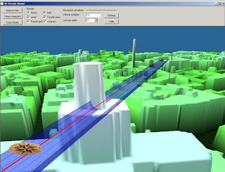
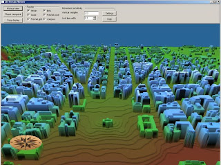
The 3D terrain view provides an interactive view of the terrain, sites, links and fresnel zones in three dimensions from any angle. The view uses the current elevation backdrop.
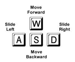
Create an elevation back drop for the area of interest and click the 3D display button on the tool bar. The initial display shows the terrain viewed from above. Click the "Manual view" button to enter the interactive display mode. The mouse movement, and the keys W, A, S, and D now control the viewpoint. To exit this interactive mode, click the left mouse button.
· Moving the mouse forward or backward moves the view point ahead or back
· Move the mouse to the left or right to rotate the view point in that direction.
· The W key moves the view point ahead in the direction it is facing (zoom in)
· The S key moves the view point away in the direction it is facing (zoom out)
· The A key moves the view point to the left perpendicular to the direction that it is facing (pan left)
· The D key moves the view point to the right perpendicular to the direction that it is facing (pan right)
All of the keys and the mouse movement can be used simultaneously to explore the display. Some dexterity and practice is required. Experience with video games is an asset here.
Click the Reset viewpoint button to return to the initial display
 3D Display Toolbar
·
The movement sensitivity slider controls the view point rate of change as the movement keys are pressed. Move the slider to the left to decrease the rate and to the right to increase it.
· The display can include the following components:
terrain - draws all the ground and water.
Links - draws the links between sites as a straight line.
Sites - draws the actual tower at all site locations in the region.
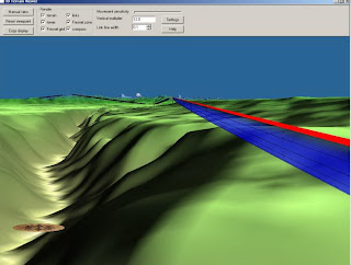
Fresnel zone - draws the 3D Fresnel zones on all links
Fresnel grid - draws the 3D Fresnel zone as a grid of lines.
Orientation compass
· The "Copy" button copies the 3D display to the windows clipboard. It can be pasted into another program.
Settings
 Click the Settings button to access additional options for the 3D display. These settings can also be accessed from the menu selection Configure - PL50 program options - 3D terrain view. Note that the link line width and vertical multiplier can be set on the toolbar or in the program options. The following options are available:
· Colors for link lines, Fresnel zones, Fresnel grids and site towers
· link line width - the value is in relative units and has no physical meaning. This number is used to create an aesthetically pleasing and informative display. The number can be set higher so the links can be viewed from a distance. It can be set to a low value to inspect links or Fresnel zone intersections at close range.
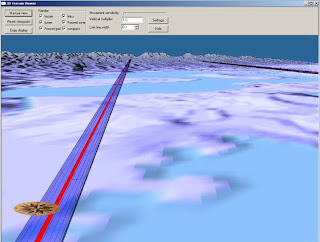
· vertical multiplier - this exaggerates all the elevations in the 3D Display and is used to make mountain ranges or valleys more prominent when viewing a large region.
· Fresnel zone reference (100% F1, 60% F1, 30% F1, F2, F4)
· Earth radius factor (K = 4/3, 1, 2/3 and infinity) - this will apply earth curvature to the terrain in the 3D Display. The terrain will fall away on all sides from the center of the display The value of k determines the effective shape of earth to display. Set K = infinity for flat earth.
Click on the green check mark when all the options are set as desired. The 3D display will be updated automatically.
3D Fresnel
3D Terrain Viewer
3 D Freznel Zone
3D Terain Viewer


 Click the Settings button to access additional options for the 3D display. These settings can also be accessed from the menu selection Configure - PL50 program options - 3D terrain view. Note that the link line width and vertical multiplier can be set on the toolbar or in the program options. The following options are available:


No comments:
Post a Comment